VIAtari (+ GLCD)
von Sleepy » Mo 24. Aug 2020, 10:09VIAtari
Introduction
Inspiration for this interface I found on Daryl's Computer Hobby Page. Daryl made Composite Video Text/Graphics Display based on ATMEGA8 and drived by VIA6522 chip. This article will show how to build, assembly and connect VIA 6522 IC to Atari and use 2 additional 8-bit parallel ports and serial interface. This is my own project build from scratch but it's nothing modern - this IC was used in C64 to communicate with disk drive. It will be used as additional PIA for manage other equipment connected to Atari.
Why?
Well, on the market you may find a few sellers which have VIA6522, but...
- this IC is discontinued, don't wait so much time, buy it!
- it's still very useful and may be good alternative for PIA 6520(6521).
- topology and registers covering PIA 6520, so you may use it as equivalent for it. (some pins
should be swapped)
- very cheap IC (~2$/piece).
Prototyping and Manufacturing
As last time (SRAM 512k extension module) I made the schematic and PCB using KiCAD
(actually I'm so surprised how good is this software!). Below you may find schematic and PCB
layout:
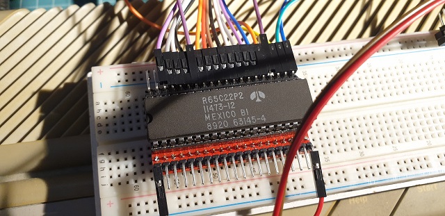
Prototyping on the breadboard:
PCB layout:
3D view
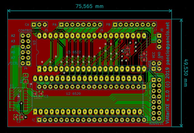
PCB without elements:
Assembled PCB:
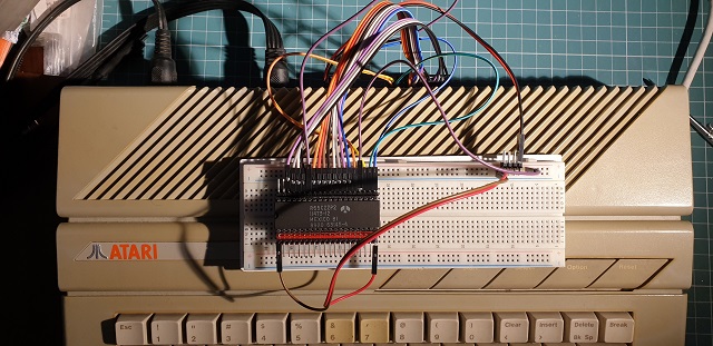
And finally, mounted into Atari:
Test procedure
Actually it's very easy and dummy test - just only for checking that 6522 working properly:
Enter the short program in BASIC interpreter and type RUN:
Now you may observe state of both ports on 6522 device. The simplest test is when you will
connect any PA/PB pin to GND...
What next?
Well many ideas to do. Now you have independent ports. For example you may steering 64 LED
matrix... using SERIAL port and many many more... I'll try to build additional display adapter as
mentioned on the beginning of the article.. but better
GLCD connected to Atari XE - the first project with VIAtari
The first project which is using VIAtari was made...
I'm glad to present the first GLCD 162x64 connected to Atari:
In order to connect GLCD I used both parallel ports - PORTB is a data bus and PORTA is for control signals. Actually I used only 5 signals, so rest may be use for other stuff.
Detail regarding wiring you may find in attached software.
In this point I need to say thanks to @mono user from http://atari.org.pl which wrote very good
PLOT procedure (topic: http://www.atari.org.pl/forum/viewtopic.php?id=16152).
Okay, showtime
First test
Second test
Pseudo"white noise" and fill test
Plot test: (point by point into memory)
The last 2 tests are making into Atari memory and result is sending as whole frame to CLCD. If you
are interested in how it's work, please analyse software...
pancio.net
Introduction
Inspiration for this interface I found on Daryl's Computer Hobby Page. Daryl made Composite Video Text/Graphics Display based on ATMEGA8 and drived by VIA6522 chip. This article will show how to build, assembly and connect VIA 6522 IC to Atari and use 2 additional 8-bit parallel ports and serial interface. This is my own project build from scratch but it's nothing modern - this IC was used in C64 to communicate with disk drive. It will be used as additional PIA for manage other equipment connected to Atari.
Why?
Well, on the market you may find a few sellers which have VIA6522, but...
- this IC is discontinued, don't wait so much time, buy it!
- it's still very useful and may be good alternative for PIA 6520(6521).
- topology and registers covering PIA 6520, so you may use it as equivalent for it. (some pins
should be swapped)
- very cheap IC (~2$/piece).
Prototyping and Manufacturing
As last time (SRAM 512k extension module) I made the schematic and PCB using KiCAD
(actually I'm so surprised how good is this software!). Below you may find schematic and PCB
layout:
Prototyping on the breadboard:
- Prototype on the BB_1_640.jpg (110.75 KiB) 2135-mal betrachtet
- Prototype on the BB_2_640.jpg (113.36 KiB) 2135-mal betrachtet
PCB layout:
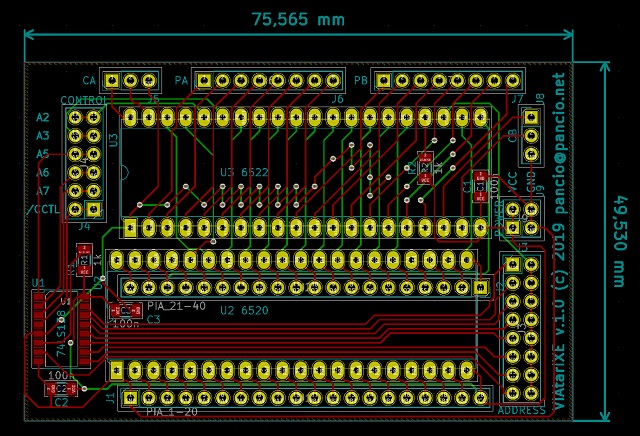
- PCB without polygons_1_640.jpg (160.72 KiB) 2135-mal betrachtet
- PCB without polygons_2_640.jpg (155.04 KiB) 2135-mal betrachtet
3D view
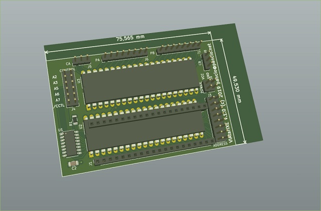
- 3D view_640.jpg (59.3 KiB) 2135-mal betrachtet
PCB without elements:
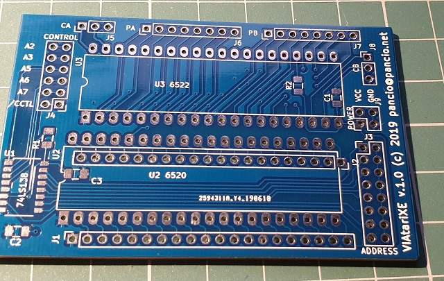
- PCB without elements_640.jpg (175 KiB) 2134-mal betrachtet
Assembled PCB:
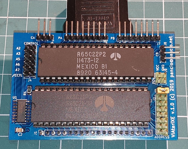
- Assembled PCB _1_640.jpg (200.28 KiB) 2134-mal betrachtet
And finally, mounted into Atari:
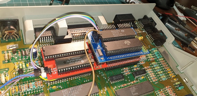
- And finally, mounted into Atari_1_640.jpg (140.7 KiB) 2134-mal betrachtet
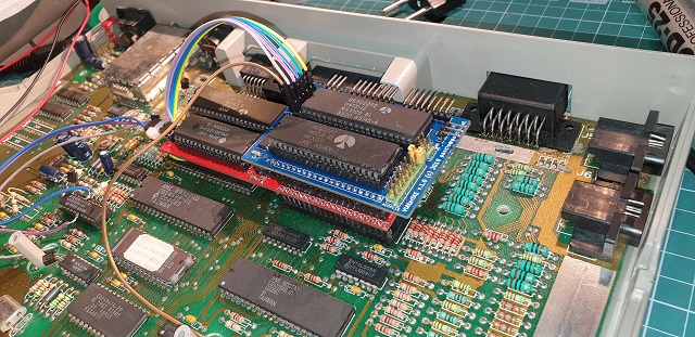
- And finally, mounted into Atari_2_640.jpg (150.46 KiB) 2134-mal betrachtet
Test procedure
Actually it's very easy and dummy test - just only for checking that 6522 working properly:
Enter the short program in BASIC interpreter and type RUN:
- Code: Alles auswählen
10 ? PEEK(54528);: ? " ";: ? PEEK(54529)
20 GOTO 10
RUN
Now you may observe state of both ports on 6522 device. The simplest test is when you will
connect any PA/PB pin to GND...
What next?
Well many ideas to do. Now you have independent ports. For example you may steering 64 LED
matrix... using SERIAL port and many many more... I'll try to build additional display adapter as
mentioned on the beginning of the article.. but better
GLCD connected to Atari XE - the first project with VIAtari
The first project which is using VIAtari was made...
I'm glad to present the first GLCD 162x64 connected to Atari:
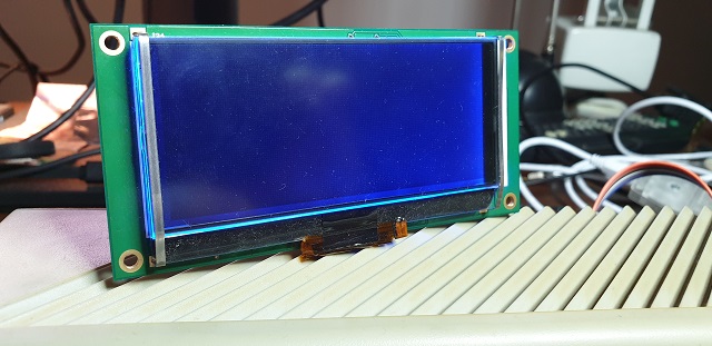
- Blank screen S1D15705 connected to Atari_640.jpg (90.4 KiB) 2134-mal betrachtet
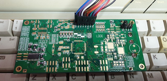
- PCB of S1D15705_640.jpg (124.84 KiB) 2134-mal betrachtet
In order to connect GLCD I used both parallel ports - PORTB is a data bus and PORTA is for control signals. Actually I used only 5 signals, so rest may be use for other stuff.
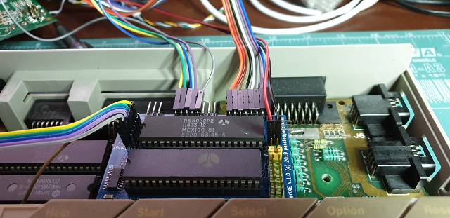
- S1D15705 connected by VIAtari_640.jpg (98.14 KiB) 2134-mal betrachtet
Detail regarding wiring you may find in attached software.
In this point I need to say thanks to @mono user from http://atari.org.pl which wrote very good
PLOT procedure (topic: http://www.atari.org.pl/forum/viewtopic.php?id=16152).
Okay, showtime
First test
Second test
Pseudo"white noise" and fill test
Plot test: (point by point into memory)
The last 2 tests are making into Atari memory and result is sending as whole frame to CLCD. If you
are interested in how it's work, please analyse software...
pancio.net