von CharlieChaplin » So 20. Dez 2020, 13:37
DeepL Übersetzung in Deutsch:
Hallo! Von dieser Seite aus wird Sikor, mit freundlicher Genehmigung von Montezuma, erklären
(Leider ist, wie Mathy erwähnt, mein Englisch sehr schlecht.
...viel zu wünschen übrig:)
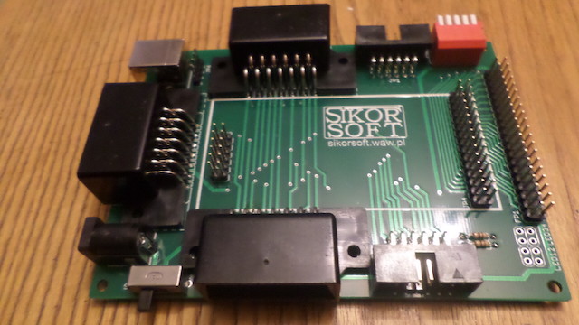
Der SuperSIO-Splitter ist die Idee eines Spritzgussgehäuses, das
universell für SIO-Geräte. Denn viele Leute fragten mich (nach
Herstellung von Hülsen für Patronen) o Möglichkeit der Herstellung von Hülsen aus einer Form
Injektion in SIO2SD, FujiNET, andere SIO - die Antwort ist für
teuer, ein solches Gehäuse für ein Gerät herzustellen. Aber die Fragen
Sie haben nicht aufgehört.
Ich beschloss, meine Erwartungen zu erfüllen und eine universelle
Gehäuse, während gleichzeitig der "letzte W
chain"-Gerät und erstellen Sie einen universellen Splitter. Annahmen
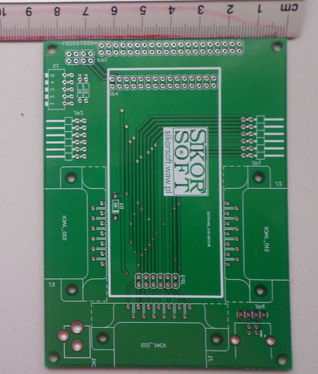
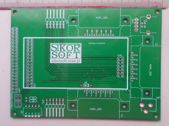
Ich habe aufgeschrieben und die richtige Person gebeten, die Fliese zu entwerfen
zum SIO-Splitter. Ich habe das Projekt "SuperSIO Splitter" genannt. A
Warum? Da ich mich entschieden habe, die Splitter-Funktionalität zu verwenden und
schaffen Sie Platz im Gehäuse für ein beliebiges, in die Steckdose eingestecktes SIO-Gerät
Erweiterungen (interne SIO). Entsprechend den Annahmen - das Gerät ist
das Innere, und das Gehäuse wird eine austauschbare Frontplatte für verschiedene
und das Design soll die bestmögliche Funktionalität bieten. Unter
einen Thread auf atariage angegeben, in dem ich die endgültige Funktionalität diskutiert habe, und
Ja:
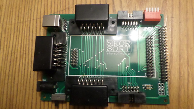
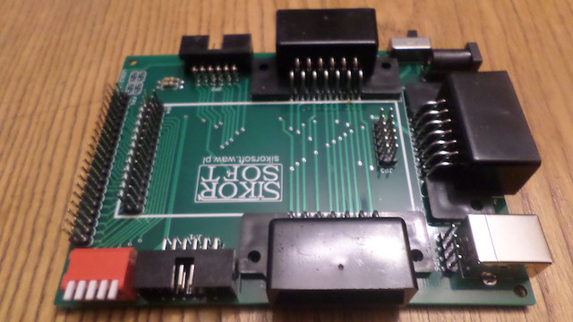
Externe Steckdosen:
- 3 SIO-Buchsen (eine "hot" für externe Spannungsversorgung)
- 2 IDC12-Stecker (SIO-Ersatz), einer heiß wie oben
- 1 USB Typ B (für SIO2PC, falls Sie diesen anschließen), mit 4 Pins für
Verbindungen im Inneren (Sie können auch eine Brücke durch sie hindurch machen, z. B.
für Arduino-Programmierung/Stromversorgung über USB)
- eine Klinkenbuchse (wahrscheinlich) für externe Spannungsversorgung (wenn
es wird für einige SIO-Geräte notwendig sein)
- einen 5-Positionen-DIPSWITCH (SW1 zum Ein-/Ausschalten
externe Spannungsversorgung, 4 für interne Verwendung mit Gerätepins
intern auf einer SuperSIO-Splitter-Hauptplatine)
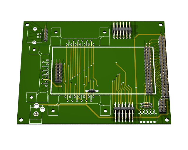
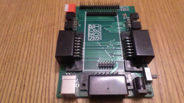
Interne Steckdosen:
- 12 SIO-Pins für SIO-Gerätekarte (2x6 Pins)
- 30-Pin-Stiftleiste (2x15) zur Erstkonfiguration von SIODEVICE und
das Signal an die Frontplatte übertragen (optional - zur Verwendung
durch den SIO-Geräteentwickler)
- 40-poliger Stecker (2x20) für Frontplattengeräte (z. B. LCD mit
Schalter, LEDs, Centronics-Schnittstelle, wenn Sie wollen...)
- 8-poliger Stecker (2x4) für LEDs (4 sind reserviert für das Signal
externe SIO-Spannungsversorgung und SIO-Spannungssignal für Geräte
(intern)
Ich habe noch nicht entschieden, ob die Frontplattenfliese (abnehmbar, Sie können
(kundenspezifisch) wird direkt auf
Pinach, lassen wir vorne etwas Platz, damit wir besser
um Platz dafür zu schaffen. Was ist Ihnen lieber?
Ich habe mich entschieden, meine Geräte mit zwei Frontplatten auszustatten, zusammen mit
das Gerät. Vielleicht gibt es ja auch zusätzliche für diejenigen, die mitmachen wollen? Wie würde ich
beschloss er, es zusammenzukleben - wie viel Platz zwischen den Platten
die Haupttafel und die Fronttafel für Sie optimal wäre (max. Reichweite
1-2cm?)
Bitte schreiben Sie Ihre Vorschläge in den entsprechenden Thread auf atariage oder hier -
Ich verfolge Ihre Antworten mit einem Google-Übersetzer.
Übersetzt mit
www.DeepL.com/Translator (kostenlose Version)
-------------------------------------------------------------------------------------
und das Ganze auf Englisch:
Hello! From this page Sikor, courtesy of Montezuma, will explain
briefly what I mean (unfortunately, as Mathy recalls, my English has
much to wish for...):
The SuperSIO Splitter is the idea of an injection mould housing that will be
universal for SIO devices. Because many people asked me (after
making casings for cartridges) o possibility of making casings from a mould
Injectionion Molding Machine for SIO2SD, FujiNET, other SIO - the answer is: it is for
expensive to make such an enclosure for one device. But the questions
they didn't stop.
I decided to meet the expectations and make a universal
housing, while at the same time preventing the pain of the "last in
chain" device and create a universal splitter. Assumptions
I wrote down and asked the right person to design the tiles
to SIO Splitter. I called the project "SuperSIO Splitter". A
Why? Because I decided to use splitter functionality and
create space in the housing for any SIO device plugged into the socket
extensions (internal SIO). According to the assumptions - the device is
internal, and the housing will have a replaceable front panel for different
The design is to provide the best possible functionality. At
indicated thread on atariage I discussed the final functionality, and
Yes:
External sockets:
- 3 SIO sockets (one "hot" for external power supply)
- 2 male IDC12 (SIO replacement), one hot as above
- 1 USB type B (for SIO2PC, if you connect it), with 4 pins to
connections inside (you can also make a bridge through them, for example
for Arduino programming/power supply via USB)
- one jack socket (probably) for external power supply (if
it will be necessary for some SIO devices)
- one 5-position DIPSWITCH (SW1 for switch on/off
external power supply, 4 for internal use with device pins
internal on a SuperSIO Splitter motherboard)
Internal sockets:
- 12 SIO pins for SIO device board (2x6 pins)
- 30-pin pin-header (2x15) for initial configuration of SIODEVICE and
transmit the signal to the front panel (optional - to use
by the SIO device designer)
- 40-pin connector (2x20) for front panel devices (e.g. LCD with
switches, LEDs, centronics interface if someone wants to ...)
- 8-pin connector (2x4) for LEDs (4 are reserved for the signal
external SIO power supply and SIO power signal for devices
(internal)
I haven't decided yet whether the tile for the front panel (removable, you can
It will be adapted to your own needs) will be mounted directly on the
pins, will we leave some space at the front so that we can better
to make room for it. What do you prefer?
I decided to add two front panels to my devices along with
device. Maybe they will also be available for additional ones? How would I
he decided to connect with tape - how much space between the plates
The main panel and the front panel would be optimal according to you (max range
1-2cm)?
Please write your suggestions in the appropriate thread on atariage or here -
I follow your answers with a google trans
Translated with
www.DeepL.com/Translator (free version)